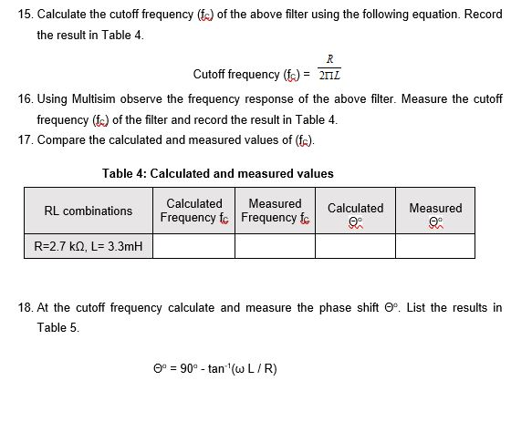

We can change the formula to make it more useful, as we usually know what cut-off frequency we want, and what the resistance (impedance) is, but what we need to calculate is what value capacitor. This is why you should only use a passive crossover or filter with the correct impedance load it has been designed to operate at. If you put the numbers into the formula, you’ll get F C of 994Hz.Īs mentioned previously, the loudspeaker impedance forms a part of the circuit, if you try the formula you will notice that increasing the impedance from 8 ohms to 16 ohms will halve the cut-off frequency and reducing the impedance from 8 ohms to 4 ohms will double the cut off frequency. Pi is the mathematical constant, you can use pi to 2 decimal places (3.14) for purposes of calculating filters. To use the formula above you need to use the capacitor value in farads, 20 uF = 0.000020 farads. In our examples above, R 1 is 8 ohms, and C 1 is 20uF (microfarads). The resistance value (measured in ohms), and the capacitance (measured in farads) determine the cut-off frequency as per the following formula:

At these higher frequencies a ‘pure’ capacitor would have no effect on the passage of signals whatsoever, unfortunately pure capacitors are theoretical, and impossible to manufacture – any capacitor used in a filter circuit will also have a small constant resistive component and some inductance also – these contribute to distortion within the signal, as well as power losses. Higher quality capacitors are designed to be closer to a ‘pure’ capacitor and minimise losses and distortion within the capacitor.Ĭalculations for 1st order High Pass Filters Beyond the cut off frequency the capacitor reactance reduces, allowing higher frequency signals to pass unhindered. F C is sometimes known as the -3dB point, where -3dB indicate half magnitude. With the capacitor and resistor being roughly equal, the system will work as a voltage divider, with approximately half the input voltage across the capacitor, and half the voltage across the resistor (loudspeaker). The point where the purple line crosses -3dB is at the cut off frequency, where the capacitor ‘resistance’ will be approximately equal to the resistor in the circuit. You can see that as the frequency reduces, the magnitude of the signal passing through the capacitor reduces. The purple line represent the magnitude of the signal that will pass through the filter. Below the cut-off frequency, the capacitor has a high resistance, effectively blocking the signal. The filter has a cut-off frequency, commonly known as F C. The cut off frequency in the diagram is 1kHz. We use dB scale for audio purposes due to how we perceive differences in volume of sound, a doubling or halving of magnitude is a significant enough change to be noticeable. V 1 is the Voltage that will be applied to the loudspeaker (R 1).
#Cutoff frequency calculator inductor full
The diagram below shows the relative magnitude of the signal at point V 1 with 0dB in the diagram indicating full signal. If you change the load resistance from 8 ohms, to 4 ohms or 16 ohms, you change how the filter circuit works. This is something to be aware of when using passive filters, that the filter DOES NOT work independently of the loudspeaker, the loudspeaker forms part of the circuit.

If you’ve ever looked at a high pass filter, and taken notice of the components, you might be wondering why you don’t have a resistor, its because the resistor in the above circuit is your loudspeaker. When combined with a resistor, you get a filter circuit, as shown in the diagram below. The Basic Building Blocks: Capacitors and InductorsĬapacitors: A Capacitor has a high ‘resistance’ (commonly known as reactance) to low frequency signals, and a low ‘resistance’ to high frequency signals. It is possible to keep splitting the audio range into smaller and smaller bands, but this can become an exercise of diminishing returns. 5-way active crossovers are not uncommon in large format PA systems in order to help cover as wide a frequency range as possible, as effectively as possible, to maximise various factors such as quality, dispersion, volume, as required by the design criteria. Common configurations are 3-way and 4-way, which allow better matching of speakers with their appropriate operating range. The most basic crossover is a 2-way crossover, which splits the signal into 2 bands. Lets’s start with a reminder of the basics, a crossover is a combination of high pass and low pass filters which split the signal into bands. Some of the basics of crossovers have been covered in this article: – here we will go into a little more detail of how passive filters work, and give you the tools to design your own.


 0 kommentar(er)
